Tadalafil appartiene alla classe degli inibitori selettivi della fosfodiesterasi di tipo 5, con un profilo farmacocinetico caratterizzato da un’emivita terminale di circa diciotto ore. Dopo somministrazione orale viene assorbito rapidamente e raggiunge concentrazioni plasmatiche massime in due ore. La biotrasformazione avviene principalmente tramite CYP3A4 con formazione di metaboliti inattivi, escreti in prevalenza con le feci. L’elevato legame alle proteine plasmatiche (>90%) assicura una distribuzione stabile. Nei confronti delle altre molecole della stessa classe, cialis compresse italia è noto per la durata prolungata dell’attività farmacologica.
Microsoft word - proposal-g3-adambertrand-yasminehovakeemian.doc
ECE 750 - T11: Component Based Software Systems
Developing an Autonomous Mobile Robot: A Component Based Approach Introduction:
Robotics is an emerging, multidisciplinary field lending itself readily to component based design including component based software systems (CBSS). By using CBSS, rapid robot development at a low cost is possible. However, in order to do so, a software framework is needed that encompasses the desired robot applications. Since the field of robotics is so vast, this project will focus on the application of component based software design for an autonomous mobile robot. Definitions:
The following terms are necessary for the complete understanding of this proposal. Absolute Position: A specific position with respect to a globally defined point of origin. An absolute position is generally unique across the entire environment. Actuator (Effector): A controllable part of the robot. Inputs to these subsystems affect the state of the robot. Angular Velocity: The rate at which an object turns or spins; the shaft of a motor, for example, may spin at a constant angular velocity. Controller (Logical): This component coordinates between all the various high-level tasks, and maintains the logical state machine of the robot. Controller (Control Systems): The component which translates the current physical state of the robot and a desired physical state into actuator inputs. Estimator: The component which translates the measurements from sensors into the current physical state of the robot. GPS: Global Position System. Using a number of satellites in orbit around the Earth, a GPS receiver can triangulate its absolute position to any location on the planet, with a reasonable degree of accuracy. Heading: The direction in which the robot is pointed. This can be absolute, or defined relative to a track, wall, etc. Interferometer: A device which can measure the properties of waves by using the interference patterns created when these waves are superimposed. LIDAR: Light Detection and Ranging. By emitting a laser beam, capturing the reflected beam, and comparing the two using an interferometer, the distance to the object that reflected the beam can be inferred. The reflected beam will be phase-shifted with respect to the emitted beam, and by tracking the amount by which the beam is shifted, distance can be deduced. Mission: A mission, in the context of robotics, is the task that the robot is designed to complete. The mission may be as simple as “Fly to a given point” or as complex as, for example, “Cooperate with other robots to place a ball into a net.” Relative Position: A position defined with respect to local point of origin. Sensor (Observer): A device which reads in information about the world surrounding the robot. Sensors provide information about the current physical state of the robot. SONAR: Sonic Navigation and Ranging. By emitting ultrasonic pulses of sound, and tracking the amount of time taken for an echo to return, a sonar device can calculate the distance to that object. State (Logical): The logical state that the robot is in, as defined by a state machine. For example: START, DRIVE, DESTINATION_REACHED. State (Physical): The physical state that the robot is in, as defined by physical parameters, and the robot model. For example: Position, Heading, Velocity. Translational Velocity (also simply Velocity): The rate at which position changes. Wheel Encoder: A sensor which is usually attached to a wheel, and can provide information about the current angular position of the wheel, either in relative or absolute terms. Problem Statement:
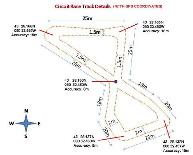
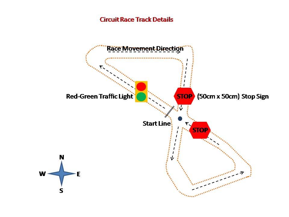
In order to narrow the scope of this project, a specific mission is needed. This mission is to build an autonomous mobile racer robot to navigate a figure-8 circuit. To add a dimension of difficulty to this task, a traffic light, two stop signs, and a dynamic obstacle at the intersection will be placed on the track. Figure 1 outlines both the layout/dimensions of the track as well as the placement of the obstacles.
Figure 1a: Circuit Race Track with dimensions Figure 1b: Circuit Race Track with obstacles Available at: http://www.eng.uwaterloo.ca/~rracing/ Available at: http://www.eng.uwaterloo.ca/~rracing/ Methodology:
The main component of the robot is the controller. The subsystems needed are sensors, actuators, and a state estimator. The sensors include sonar, wheel encoders, GPS, and a laser rangefinder, but many other sensors are available. The actuators (also called effectors) are the controllable aspects of the robot and include the drive motor and steering. The controller is a software module which reads in sensor data and drives the actuators accordingly based on the output of state estimator. Figure 2 contains a high level system design. Figure 2: High Level System Design of Autonomous Mobile Robot.
This will be a purely software project and therefore a simulation environment will also need to be developed. This environment (grey box in figure 2) will contain the world in which the robot will operate and all the associated states. As such all of the sensors and actuators will have to be simulated within the confines of our world. The robot will begin at an idle state with all sensors and actuators constructed. It will be assigned to an environment depending on its mission or task. Initially, robot motion will be developed and tested with a random walk mission in mind. If proven to be successful, further environments and missions can be considered. The following is a state diagrams for a simple random walk. One will be developed for the figure 8 track and other missions/tasks that we implement in the future.
Figure 3: Autonomous Mobile Robot State Diagram for a Random Walk Mission
As the mission may potentially change, additional sensors and actuators may be needed. For example to complete the figure 8 track, a vision control component with a camera would be needed. With a simple change to the controller to include vision sensor data in state estimation, this addition can be made. Components: The following components are defined in the system diagram in Figure 2. Motor: This component will control the angular (rotational) and translational (forward and back) velocity based on the control values given by the controller. Steering: This component will control the heading of the robot based on information received from the controller, allowing the robot to turn. Wheel encoders: These components measure the amount that a wheel has turned. Coupled with timing information, the current speed of the robot can be deduced and this will help the controller decide whether to accelerate/decelerate. GPS (Global Positioning System): This component will be used by the robot to find its current location within the environment. Sonar: This component is used to measures distances to objects/obstacles in the environment near the robot using a pulse of sound at an ultrasonic frequency, and listening for the echo generated by that pulse and measuring the time of flight. Laser (LIDAR): This component will also be used to measure the distances to objects near the robot as well by emitting a laser pulse, and using an interferometer on the reflected beam to deduce the distance to that object. State Estimation and Control: This component estimates the current state of the robot (different state from the state machine), and determines what control input to use to achieve the desired state. Results Expected:
The overall objective is to successfully navigate the figure-8 course and all inclusive obstacles. In order to track the movement of the racer robot, we hope to construct a graphic display (GUI) that will help envision the mission. To be able to make the task of building this robot more realistic, a certain noise factor must be part of the environment. In the ‘real world’, the sensors, actuators and controllers need to have a certain degree of noise tolerance. We hope to bring this aspect of noise to the environment and simulation data. At the same time, this simulation data must be kept within real bounds. Lastly, in order to define this robot as truly modular, we want to demonstrate that the addition of sensors and other subsystems would be possible with this system architecture with slight modifications to the controller. To analyze our robot from a performance perspective, we will consider the following performance metrics. The time to complete the mission or task will be the fundamental performance metrics. A lower time, while still maintaining proper and efficient operation, is desirable. Another performance metric is the smoothness of the path. A robot that operates on a smooth (as opposed to jagged) path is much more efficient. Lastly, a robot will always experience some amount of noise from its environment. The robustness of the robot to noise will be measured as well. Since purely objective measurements of metrics such as robustness and smoothness are difficult, some measure of subjective measurement will be used to evaluate the performance of the system. Resources Needed:
The system design was established based on the analysis of the figure 8 track mission. For example, the obstacles in the course made the use of a laser and sonar sensor, or similar detection/ranging sensor, a necessity. A better understanding of the resources needed will emerge as the development progresses.
Schedule: Table 1: Schedule of Tasks for ECE 750 Project Design Documentation Development & Simulation Develop Sensors and Simulate Sensor Data July 6 ~ July 10, 2009 Develop Environment Testing, Debugging & Finalization Presentation 1 Presentation 2 Final Report Design Documentation Development & Simulation Testing, Debugging & Finalization Presentation 1 Presentation 2 Final Report Figure 4: Gantt Chart Outlining Schedule Made References:
[1] A. Brooks, T. Kaupp, A. Makarenko, S. Williams, and A. Oreback, “Towards
component-based robotics,” in IEEE/RSJ International Conference on Robots and Intelligent Systems. (Edmonton, Alberta, Canada, August, 2005, pps. 3567–72).
[2] D. B. Stewart, and P. K. Khosla, “Rapid Development of Robotic Applications Using
Component-Based Real-Time Software,” in Proceedings of the 1995 IEEE/RSJ International Conference on Intelligent Robots and Systems (IROS’95). (Pittsburgh, PA, August 5–9, 1995, pps. 465–470)
Oracle SQL Query Tuning Hints WHERE Clause Try to avoid operations on database objects referenced in the WHERE clause. Given Query Alternative WHERE SUBSTR(ename,1,3) = WHERE ename LIKE 'SCO%'; WHERE ename = NVL (:name, WHERE ename LIKE NVL (:name, '%'); WHERE TRUNC (hiredate) = WHERE hiredate BETWEEN TRUNC (SYSDATE) AND TRUNC (SYSDATE) + .99999; WHER
NCTTA Board of Directors August 26, 2012 In attendance: Willy Leparulo (WL), Randy Kendle (RK), David Del Vecchio (DD) late, Wanda Wong (WW) late, Joseph Wells (JEW) late, Kevin Li (KL), Ed Toomey (ET), Chris Wang (CW) Not in attendance : Seemant Teotia, Linda Leaf, Nelson Gore, Brayden Glad, Michael McFarland, Abe Behnam MTG started at 8:02pm Meeting Minutes from July 25th approved 5
 Mission: A mission, in the context of robotics, is the task that the robot is designed to
 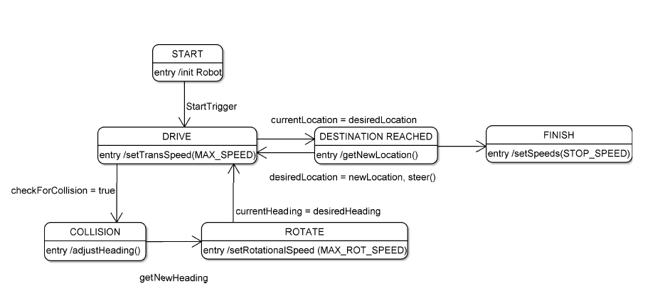 Figure 3: Autonomous Mobile Robot State Diagram for a Random Walk Mission