Tadalafil appartiene alla classe degli inibitori selettivi della fosfodiesterasi di tipo 5, con un profilo farmacocinetico caratterizzato da un’emivita terminale di circa diciotto ore. Dopo somministrazione orale viene assorbito rapidamente e raggiunge concentrazioni plasmatiche massime in due ore. La biotrasformazione avviene principalmente tramite CYP3A4 con formazione di metaboliti inattivi, escreti in prevalenza con le feci. L’elevato legame alle proteine plasmatiche (>90%) assicura una distribuzione stabile. Nei confronti delle altre molecole della stessa classe, cialis compresse italia è noto per la durata prolungata dell’attività farmacologica.
F.p.doc
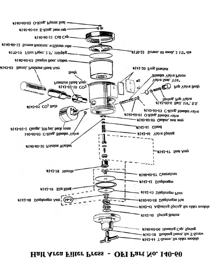
OFI Testing Equipment – Half Area Filter Press Instructions Part # 140-60
FILTER PRESS, HALF AREA OFI Part No. 140-60
The OFI Half Area Filter Press or Mini-press, consists of a modified low pressure regulator with a CO2 bulb pressurizing assembly and a filtration cell body. A rubber diaphragm boot contains the fluid and separates it from the pressurizing gas. This enables the unit to be operated inverted which negates the effect of particles settling on the filter medium prior to pressurization. The top edge of the boot acts as a gasket to provide a seal to the filter paper and the end cap. As the name implies the filtration area is only half the API standard, 7.1 ±0.1 in3 (4580 ±60 mm3) so all filtrate volumes must be doubled in order to comply with standard low pressure filtration analysis. The compactness of the OFI Mini-press allows it to be easily carried in all of the field kits, and it provides an accurate means of determining the filtration and wall-building characteristics of a drilling fluid. Equipment: #140-60-01 O-Ring, for bleeder valve
#142-44 T-Screw, for older models) (0750-0016)
#142-45 Adjusting Spring, for older models(0761-0025)
#140-60-06 Housing Cap, Spring, (0799-1215)
#140-60-09 Gasket, for seat assembly (1408-0086)
#143-00-6 Ball, 1/4 inch, stainless steel
#143-01-1 Gauge, 200 psi, back connection
#143-02-10 CO2 Puncture Head Assembly, OFI
#140-60-12 Screen Retainer, with filtrate tube
#143-02-13 O-Ring, for OFI Puncture Head Assy
#143-03-14 O-Ring, for OFI Puncture Pin Holder
#143-03 Barrel, for OFI Puncture Head Assembly
#153-18 Cylinder, Graduated, 10 ml x 2/10 ml,
#170-19 Filter Paper, 2 1/2 inch, 100/pkg
#170-23 Screen, 60 mesh, 2 1/2" diameter
Note: CO2 Bulbs must be ordered separately Part No. 143-05, packaged 10/pkg (UN1013)
OFI Testing Equipment – Half Area Filter Press Instructions Part # 140-60
Procedure: 1.
Unscrew the cell cap from the cell body.
Seat the rubber boot around the top edge of the body to ensure a tight seal.
Fill the rubber boot to within 1/16" (1.6 mm) of the top with fluid.
Place a sheet of Filter Paper across the top of the boot.
Mount the cell assembly on a wall bracket and place a 10 ml graduated cylinder under the filtrate tube to catch the filtrate.
Pressurize by pushing the cell valve toward the back of the cell and rapidly screw the regulator T-screw
into the regulator so that 100 ±5 psi (690 ±35 kilopascals) is applied in 30 seconds or less to the cell
body. The test time period begins at the time of pressure application.
At the end of 30 minutes, bleed off the CO2 from the cell and relieve the pressure on the rubber boot by
pushing the cell valve toward the front of the cell.
Record the volume of filtrate collected to the nearest 0.1 cm3 as the API filtrate. Correct the filtrate volume collected to a filter area of 7.1 square inches by multiplying the volume by two (2). Also record the temperature of the fluid in °F (°C) , the time of the test and the pressure used.
With the cell valve pushed toward the front of the cell, unscrew the T-screw to its maximum outward
position and remove the end cap. Save the filtrate for chemical testing.
Use extreme care to save the filter paper with a minimum of disturbance to the cake. Gently wash the filter cake on the paper and measure the thickness of the filter cake to the nearest 1/32" (9.8 mm). Report cake characteristics as hard, spongy, firm, etc.
Remarks:
1.
If the pressure gauge registers insufficient pressure after the T-screw has been screw into the regulator, the CO2 bulb is probably exhausted. Push the cell valve toward the front of the cell and return the T-screw to its maximum outward position. Remove the barrel from the pressure unit and discard the spend bulb. Place a new CO2 bulb into the barrel and screw the barrel back into the puncture assembly. Do not over tighten as this will result in a loss of CO2 gas.
Thoroughly clean and dry the filter press unit immediately after each use.
Exercise care when handling the cell when it is filled with fluid so that the valve is not accidentally opened
before the cell cap is screwed into place.
Protect CO2 bulbs from sunlight and other sources of heat.
OFI Testing Equipment – Half Area Filter Press Instructions Part # 140-60
Lubricate bleeder valve o-rings with a film of silicone grease for extended life.
OFI Testing Equipment – Half Area Filter Press Instructions Part # 140-60
For more information, please contact us:
ExpotechUSA 10700 Rockley Road Houston, Texas 77099 USA
Stefan Müller-Hülsbeck, M.D., PhD, FCIRSE, FICA P r o f e s s o r o f R a d i o l o g y Ev.- Luth. Diakonissenanstalt zu Flensburg Zentrum für Gesundheit und DiakonieAkademisches Lehrkrankenhaus des Universitätsklinikums Schleswig-Holstein Institut für Diagnostische und Interventionel e Radiolgie / Neuroradiologie Telefon 0461 812 1801, Fax 0461 812 1801 Education in Medicine
Medication Guide Non-Steroidal Anti-Inflammatory Drugs (NSAIDs) (See the end of this Medication Guide for a list of prescription NSAID medicines.) What is the most important information I should know about medicines called Non-Steroidal Anti-Inflammatory Drugs (NSAIDs)? NSAID medicines may increase the chance of a heart attack or stroke that can lead to death. This chance increases: N
 OFI Testing Equipment – Half Area Filter Press Instructions Part # 140-60
For more information, please contact us:
ExpotechUSA 10700 Rockley Road Houston, Texas 77099 USA
OFI Testing Equipment – Half Area Filter Press Instructions Part # 140-60
For more information, please contact us:
ExpotechUSA 10700 Rockley Road Houston, Texas 77099 USA