Tadalafil appartiene alla classe degli inibitori selettivi della fosfodiesterasi di tipo 5, con un profilo farmacocinetico caratterizzato da un’emivita terminale di circa diciotto ore. Dopo somministrazione orale viene assorbito rapidamente e raggiunge concentrazioni plasmatiche massime in due ore. La biotrasformazione avviene principalmente tramite CYP3A4 con formazione di metaboliti inattivi, escreti in prevalenza con le feci. L’elevato legame alle proteine plasmatiche (>90%) assicura una distribuzione stabile. Nei confronti delle altre molecole della stessa classe, cialis compresse italia è noto per la durata prolungata dell’attività farmacologica.
Digitalas.lt
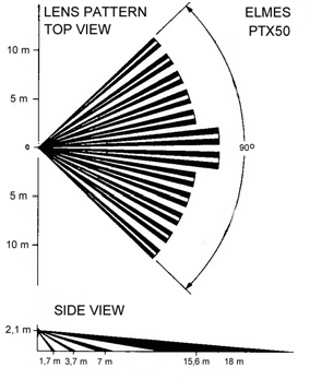
Wireless passive infrared (PIR) motion detector PTX50 (GB)
The detector is designed for application in wireless alarm, security systems, access control. It features infrared detection
pulse count, sophisticated power saving system allowing three years operation on single alkaline 9V battery, KEELOQ® hopping code highest security encrypted transmission, wide angle 90° lens with 15m detection range and optional vertical or animal curtain lenses, sensivity temperature compensation, high radio interference immunity, tamper alarm, low battery warning and blinking LED for self test indication on battery connection. Built-in 433,92 MHz radio transmitter suits the detector to operate with all Elmes receivers including most recommended multi-channel receivers CH4H, CH8H and CH20H. Modes of operation Normal(DIP switch 3 in OFF position). Alarm transmissions (three in random time intervals) are
triggered on movement detection in protected area after minimum of two minutes movement absence. If movement is more frequent than two minutes, the detector will switch to battery saving mode and not alarm until detection is made after any two minutes of quietness.
Test (DIP switch 3 in ON position). Alarm transmission is triggered on each movement detection in
protected area without switching to battery saving mode. Low battery warning and tamper alarm
The detector’s battery voltage is monitored. Its drop to 7V results in warning being sent to receiver
with any next alarm transmission. At the receiver’s side the warning information is displayed by blinking receiver’s LED (see the receiver’s manual). It will continue so until battery is replaced. Batteries should replaced every three years even no low battery warning is signalled.
The tamper alarm is triggered every two minutes on detector’s box opening and lasts for as long as
the box remains opened. Programming to receiverFig. 1 1. Set the DIP switches 3 and 4 to ON allowing test operation of the detector with LED set to ON. 2. Install 9V alkaline or lithium battery and close detector’s box. Wait approx. 1 minute till end of the self test (LED stops blinking). 3. Connect the receiver to power supply and place it within no less than 0,5 metre distance from the detector. 4. Set the receiver to learning mode (see receiver’s programming instructions and selecting required channel details). 5. Activate two alarm transmissions from the detector (e.g. moving hand over detector’s lens). 6. Blinking receiver’s LED indicates properly programmed detector to the receiver. If failed, then repeat points 4 and 5 above. Once programmed to the receiver, the detector’s alarm transmissions will set on receiver’s output relay in the channel the detector is programmed to. Tamper alarm of the detector will be active in the last channel output of the receiver. Installation and testing Avoid installing the detector in front of any reflective surfaces such as mirrors and windows as they may reflect unwanted sunlight and cause false alarms. Keep it away from strong airflow, ventilation holes and air ducts. Moisture and oil also affect proper operation of the detector. Do not install the detector close to heaters, open fire premises nor within the maximum range of the transmitter. Care should also be taken not to install the detector close to radiating cables and metal surfaces that may cause interference and obstruct radio link with the receiver. Two or more wireless detectors installed close to each other or in one room could cause radio interference and thus be eliminated as reliable source of alarm detection. Therefore, care should be taken to avoid triggering alarm transmission from two or more detectors at the same time. The detector should be installed 2 to 3 metres above floor level. Each location should be walk tested and the detector pulse count individually set to required speed of setting alarm on. Setting the pulse count switches (Fig.2 table) to 1 will generate relatively fast alarm transmission thus making the detector less immune to false alarms. Selecting 2 or 3 pulses for slower alarm speed is recommended for most standard applications of the detector. Depending on location and detection coverage needs the detector’s vertical adjustment may be set in two ways. First, by moving the detector’s board to the desired maximum or minimum far range coverage gauge marked on board versus the board’s screw (± 6 degrees adjustment). Second, by installing the detector on the back side bottom part which will reduce the far range of detection by 9 degrees. Setting the detector to normal operation requires fixing of the detector’s box to wall with the use of included installation screws, setting the walk test to OFF (sw. 3), screwing the decoder’s board and closing box with provided security screw. It is recommended to test wireless alarm installation regularly, e.g. once a month. Changing lenses While changing the detector’s lens middle edge triangle groove should be upwards positioned matching centring mark of the lens window inside the box also, different size of the fixing clips of the plastic sleeve should match proper holes in the box. Specification of the PTX50 detector Fig. 2
- 9V alkaline battery operation with ultra low power requirement (0,015mA at standby),
- dual infrared sensing element with programmable pulse count (1-2-3-5), - high quality multi-beam Fresnel lens with 90° detection angle coverage and protective sleeve,
- internal and external detection range adjustment,
- battery voltage monitoring and the detector tamper switch,
- CE <5mW/433,92MHz transmitter with 20-50m operating range depending on location, - RF interference immunity better than 10V/m over 0,1 to 1 GHz range, - detector’s sensivity temperature compensated, - indoor use with operating temperatures 0 to +40 deg. Celsius.
Elmes Electronic declares that the product has been manufactured and tested to comply to the following standards: EN 60950-1 :2001 electric safety, EN 301 489-1 V1.4.1 (2002-08) EMC for radio equipment, EN 301 489-3 V1.2.1 (2002-08) EMC for Short Range Devices, EN 300 220-3 V1.1.1 (2000-09) EMC and Radio Spectrum Matters.
Limited manufacturer’s warranty Elmes Electronic products carry manufacturer’s one year limited warranty as from date of purchase. The warranty is limited to the replacement of faulty original parts or repair defects of improper manufacture. Damage, faulty use or improper handling by the user or installer as well as any changes in product’s hardware or software caused by the user or any other unauthorised person violets the warranty and all due repair costs will be charged. In all cases, the customer pays costs of delivery to and from the manufacturer of the products to be serviced. Elmes Electronic shall not bear any liability for any personal or material damage resulting from its any product direct, indirect or partial failure to operate properly. KEELOQ® is a registered trade mark of Microchip Technology Inc., USA. ELMES ELECTRONIC, tel. (+4871) 7845961, fax (+4871) 7845963, e-ma. .Elmes Electronic 2004. All rights reserved.
Preventing illness Infections are common in children and often lead to il ness. At home, children are reasonably wel protected from infectious diseases because they don’t come in contact with many people. The adults they meet are general y immune to many childhood il nesses because they had them as children or they have been vaccinated. Because of this immunity, adults cannot transmit th
Mother and Child Week Planning Tool 1. DISTRICT PROFILE Name of District: Total Population: ______________ million Urban Population (wards): ___________________ million Rural Population (villages): ____________________ million Number of union councils: ___________ Number of Total FLCFs ________________. Number of FLCFs involved in LHWs Program__________________ Number of FLCF

 Wireless passive infrared (PIR) motion detector PTX50 (GB)