Tadalafil appartiene alla classe degli inibitori selettivi della fosfodiesterasi di tipo 5, con un profilo farmacocinetico caratterizzato da un’emivita terminale di circa diciotto ore. Dopo somministrazione orale viene assorbito rapidamente e raggiunge concentrazioni plasmatiche massime in due ore. La biotrasformazione avviene principalmente tramite CYP3A4 con formazione di metaboliti inattivi, escreti in prevalenza con le feci. L’elevato legame alle proteine plasmatiche (>90%) assicura una distribuzione stabile. Nei confronti delle altre molecole della stessa classe, cialis compresse italia è noto per la durata prolungata dell’attività farmacologica.
Ba_gb.fm
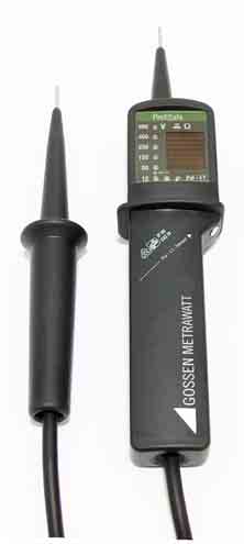
PROFISAFE400 PROFISAFE690 Voltage-Continuity Tester
GMC-I Messtechnik GmbHSüdwestpark 15 90449 Nürnberg • GermanyPhone+49 911 8602-111 Fax
E-Mail [email protected]
2 Rectangular LED (green) for continuity check,
3 7 round LEDs (red) for two-pole voltage testing
PROFISAFE400: 12 … 400 V PROFISAFE690: 24 . 690 V
4 2 round LEDs (red) for indicating AC/DC/ polarity
5 Triangular LED (red) "Pol-L1" for phase and
6 Accessible electrode "Pol-L1-Sensor" for
7 Solar cell for charging the integrated lithium
The PROFISAFE is a two-pole voltage tester in accordance with EN/IEC 61243-3 (VDE 0682 part 401) with LED display. You can use the PROFISAFE to measure DC and AC voltages PROFISAFE400: 12 . 400 V PROFISAFE690: 24 . 690 V. Furthermore you can determine polarity, phase and phase sequence and perform continuity tests up to 500 k. The energy for the additional func- tions (continuity/phase sequence/phase) is sup- plied by an integrated storage lithium battery which is charged by a high-performance solar cell, even at a minimum light level. The intrument does not require any batteries. The proprietary energy source is not necessary for voltage testing. Thanks to its high degree of protection (IP 65) the PROFISAFE may even be used in rain.
You have chosen an instrument which provides you with a high level of safety. The PROFISAFE voltage tester has been approved by VDE test authorities for application of VDE GS marking. When used for its intended purpose, the safety of the operator, as well as that of the instrument, is assured. In order to maintain flawless technical safety conditions, and to assure safe use, it is imperative that you read these operating instructions thoroughly and carefully before placing your instrument into service, and that you follow all instructions contained therein.
The voltages indicated on the PROFISAFE are nominal values. The voltage tester may only be used in systems working with the specified nominal voltage range.
Faultless indication of display values is only guaranteed between –10 ° and +55 °C.
Hold the instrument by its handles only, to avoid covering the display and touching the test electrodes before and during tests.
Just before they are used, voltage testers need to be checked to ensure they function correctly.
Carry out the function test and check the instrument at a familiar voltage source – e.g. a 230 V socket. If the display of one or several systems fails in the course of testing, the instrument may no longer be used.
The PROFISAFE must not be switched on for more than 30 seconds.
For the determination of phase conductors and phase sequence by means of the acces-sible electrode, the perceptibility of the display may be impaired, e.g. when using protection means against direct contact, in unfavourable locations, for example on wooden ladders or insulating floor coverings, as well as in unfavourable lighting conditions and in an improperly grounded AC voltage system.
The voltage tester may only be dismantled by authorized personnel.
Voltage testers must be clean and dry.
The innovative concept of the PROFISAFE allows for voltage measurements even with entirely depleted storage batteries. Thanks to the solar cell and the permanently integrated lithium storage battery the PROFISAFE is always ready for conti- nuity tests without the need for battery replace- ment. Please proceed as follows to test the correct functioning of the PROFISAFE:
To test the functions and the proprietary energy source, put the test electrodes together. The rect-angular green LED (continuity test) lights up per-manently. Subsequently, test the instrument at a familiar voltage source, e. g. a 230 V mains outlet.
If one of the LED does not light up, theinstrument may no longer be used.
If the green LCD, after putting the test electrodes together, flickers or does not light up, you have to recharge the storage battery (scontinuity tests. Voltage tests can still be con-ducted without the storage battery.
Voltage testing is always active. PROFISAFE400 U 12 V:
PROFISAFE690 U 24 V:
PROFISAFE400 / PROFISAFE690 U = 0 V:
Switch-over to continuity test, continuity is indicated by green LED
The maximum allowable on-time for volt-age testing is 30 seconds.
Both lower 12 V/24 V LEDs () light up alterna-tively when an AC voltage within the nominal volt-age range is applied to both test electrodes. The LED chain located above lights up according to the voltage applied.
When a DC voltage within the nominal voltage range is applied to both test electrodes, one of the lower 12 V/24 V LEDs () and the LED chain located above light up according to the voltage
applied. Polarity is determined as follows: The "+" 12 V/24 V electrode lights up when the test probe marked "+" is connected to the positive pole.
The PROFISAFE is equipped with an accessible electrode "Pol-L1-Sensor", and a triangular LED for phase testing and phase sequence indication.
While working with the accessible elec-trode the perceptibility of the display may be impairedfety Pre-cautions).
Tests with the accessible electrode only function in properly grounded AC voltage systems with volt-ages as from approx. 165 V towards earth.
The phase conductor is identified by establishing con-tact between one of the two test probes and the con-ductor, and by simultaneously touching the accessible electrode "Pol-L1-Sensor" with your finger. If the triangle lights up, the conductor is energized.
To determine the phase sequence between two phases in a grounded 230/400 V 3-phase system by applying both test electrodes and touching the accessible electrode, proceed as follows:➭
Search for the phase conductors using one pole (see phase test).
Apply both test electrodes to two phase con-ductors (display value: approximately 400 V).
Touch the accessible electrode with your finger.
If phase L1 is applied to the test probe marked + L1 and phase L2 to the other test probe, the trian-gle lights up if rotation is clockwise. If the triangle does not light up, the direction of rotation is counter-clockwise. If 230 V is displayed instead of 400 V, the neutral conductor may have been con-tacted with one of the test probes.
Apply the test electrodes to the conductor to be tested. The rectangular green LED lights up at a resistance of 0 to about 500 k. The green rectan- gle lights up if the test probe of the PROFISAFE marked "+" is applied to the anode of a semicon- ductor. Otherwise the semiconductor is connected in the reverse direction.
The instrument is immediately ready for the next test. Voltage readings always take priority (see
9 LEDs for voltage, continuity, phase and phase sequence
PROFISAFE400: 12 . 400 V AC/DC in incre- ments of 12, 24, 50, 120, 230, 400 V PROFISAFE690: 24 . 690 V AC/DC in incre- ments of 24, 50, 120, 230, 400, 690 V
PROFISAFE400: 117 k PROFISAFE690: 202 k
Extract from table on the meaning of IP codes
Rubber insulated flexible cable H07RN-F, 1m
If the green LED does not flash or light up when putting together the test probes, you have to recharge the battery. Place the instrument in a light source (e.g. on a window sill) with the display field facing upward. Due to the high-performance solar cell, the PROFISAFE wil be fully functional within a short period of time (approx. 15 minutes). Perform the function test before putting the instrument back into operation (see 3.1).
Please do not use halogen lamps for charging, otherwise the device might be damaged.
The voltage tester should be kept dry and clean. The plastic housing can be cleaned with a cloth dampened with isopropyl alcohol or soapy water.
Device Return and Environmentally Compatible Disposal
The instrument is a category 9 product (monitoring and control instrument) in accordance with Elek-troG (German Electrical and Electronic Device Law). This device is not subject to the RoHS directive. We identify our electrical and electronic devices (as of August 2005) in accordance with WEEE 2002/96/EG and ElektroG with the symbol shown to the right per DIN EN 50419 . These devices may not be disposed of with the trash. Please contact our service department regarding the return of old devices.
Repair and Replacement Parts Service DKD Calibration Center* and Rental Instrument Service
GMC-I Service GmbHService Center Thomas-Mann-Straße 2090471 Nürnberg, GermanyPhone +49 911 817718-0Fax
This address is only valid in Germany. Please con-tact our representatives or subsidiaries for service in other countries.
Quantities DKD – K – 19701 accredited per DIN EN ISO/IEC 17025:2005Accredited measured quantities: direct voltage, direct current values, DC resistance, alternating voltage, alternating current values, AC active power, AC apparent power, DC power, capaci-tance, frequency and temperature
GMC-I Messtechnik GmbHHotline ProduktsupportPhone +49 911 8602-0Fax
Edited in Germany Subject to change without notice A pdf version is available on the internet
Psychiatry 1 MCQ’s With personality disorders, the following are true EXCEPT Cluster ‘C’ represents the ‘anxious & fearful’ group of personality disorders Personality disorder is a ‘Axis III’ diagnosis Both Anti-social and Histrionic personality disorders are found in Cluster ‘B’ A person with Avoidant personality disorder is socially withdrawn but actually would li
 PROFISAFE400
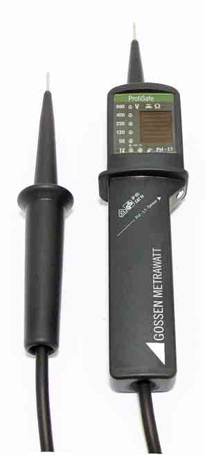 2 Rectangular LED (green) for continuity check,
3 7 round LEDs (red) for two-pole voltage testing
PROFISAFE400: 12 … 400 V
2 Rectangular LED (green) for continuity check,
3 7 round LEDs (red) for two-pole voltage testing
PROFISAFE400: 12 … 400 V The PROFISAFE is a two-pole voltage tester in
 Device Return and Environmentally Compatible Disposal
The instrument is a category 9 product (monitoring and control instrument) in accordance with Elek-troG (German Electrical and Electronic Device Law). This device is not subject to the RoHS directive.
Device Return and Environmentally Compatible Disposal
The instrument is a category 9 product (monitoring and control instrument) in accordance with Elek-troG (German Electrical and Electronic Device Law). This device is not subject to the RoHS directive.